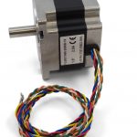
86STH65 NEMA-34 Bipolar Gearless Stepper

This NEMA-34 motor generates 34 kg-cm of holding torque at 2.8 Amps. It comes with the rear shaft exposed, so you can mount an encoder or shaft coupler. See the “Compatible Products” tab for a complete list of attachments.
When connected to a 1067 – PhidgetStepper Bipolar HC, the 3335 has a maximum speed of 200 RPM. See the “Compatible Products” tab for wiring details.
Connection
This motor must be controlled by a constant current or chopper drive controller. You can find a list of suitable controllers on the Compatible Productstab. There you will also find compatible attachments such as encoders, mounting hardware, and transmission hardware.
Warning
|
Connecting the motor directly to a power supply will destroy the motor and void the warranty. If you want to check your motor make sure it is connected to a constant current / chopper drive controller. This motor is large enough that the back EMF generated from stalling or changing directions could easily damage your motor controller. If you’re planning on using this motor in high-speed or high-torque applications, feel free to contact us for advice. |
Product Specifications
| Motor Properties | |
|---|---|
| Motor Type | Bipolar Stepper |
| Manufacturer Part Number | 86STH65-2808B |
| Step Angle | 1.8?° |
| Step Accuracy | ?± 5 % |
| Holding Torque | 34 kg?·cm |
| Rated Torque | 30 kg?·cm |
| Maximum Speed (w/1067 Motor Controller) | 200 RPM |
| Acceleration at Max Speed (w/1067 Motor Controller) |
1E+06 1/16 steps/sec?² |
| Electrical Properties | |
| Recommended Voltage | 30 V DC |
| Coil Resistance | 1.4 ?© |
| Rated Current (Series Wiring) | 2 A |
| Rated Current (Parallel Wiring) | 4 A |
| Phase Inductance | 3.9 mH |
| Physical Properties | |
| Shaft Diameter | 12 mm |
| Rear Shaft Diameter | 3.9 mm |
| Mounting Plate Size | NEMA – 34 |
| Weight | 1.8 kg |
| Number of Leads | 8 |
| Wire Length | 400 mm |
Documents
- Stepper Motor and Controller Primer
- Mechanical Drawings
- Download 3D Step File
Projects
- Motor Music: Play MIDI Files using Phidget Stepper Motors (June 1, 2015)
- How To Avoid Resonance Issues in Stepper Motors (July 28, 2014)
- Using Steppers In High-Energy Applications (June 3, 2014)
- Steppers with Encoders: When Open-loop Control Is Not Enough (May 13, 2014)
Motor Controllers
This motor must be controlled by a stepper motor controller. These diagrams show to wiring configurations: series and parallel. Series wiring will result in higher torque when the motor is stopped or at low speeds. Parallel wiring will provide better torque at higher speeds, but less torque overall. Since the current in parallel mode is split between two paths, the current rating is doubled. When connecting motor wires to one another, you must solder or screw clamp them together rather than just twisting them together.
Note: Make sure to unplug the power cord from the motor controller before switching wires around.
The following stepper controllers can be used to drive this motor:
| Product | Controller Properties | Electrical Properties | ||
|---|---|---|---|---|
| Part Number | Motor Position Resolution | Stepper Velocity Resolution | Stepper Velocity Max | Available Current per Coil Max |
| 1067_0B | 1⁄16 Step (40-Bit Signed) | 1 1/16 steps/sec | 250000 1/16 steps/sec | 4 A |
| STC1000_0 | 1⁄16 Step (40-Bit Signed) | 1 1/16 steps/sec | 115000 1/16 steps/sec | 4 A |
Encoders
The rear shaft of this motor can be equipped with an encoder for applications where you need to keep track of the exact position, velocity, or acceleration of the motor. The mounting holes on the back of this motor are compatible with the following encoders:
| Product | Encoder Properties | ||
|---|---|---|---|
| Part Number | Output Circuit Type | Encoder Resolution | Encoder Speed Max |
| 3531_0 | Push-Pull (Single-Ended) | 300 CPR | 6000 RPM |
Shaft Couplers
If you need to connect the main shaft of this motor to the shaft of another device, you can use a shaft coupler:
| Product | Physical Properties | |||
|---|---|---|---|---|
| Part Number | Inner Diameter | Material | Coupling Rated Torque | Coupling Rated Speed |
| 3428_0 | 12 mm | Aluminium | 60.7 kg?·cm | 16000 RPM |
| TRM4317_0 | 12 mm | Aluminum | 35.7 kg?·cm | 12000 RPM |
| TRM4318_0 | 12 mm | Aluminum | 611.8 kg?·cm | 4000 RPM |
Pulleys and Sprockets
If you’re using this motor to drive a rotary system that requires a lot of torque, you may be interested in pulleys and sprockets. By using a two pulleys or sprockets of different sizes, you can increase the gear ratio of the motor. Pulleys and sprockets can also be used to transmit the motor’s rotation over a long distance. For more guidance on building a transmission system, visit our Rotary Motion Primer. Here is a list of our 12mm bore pulleys and sprockets: