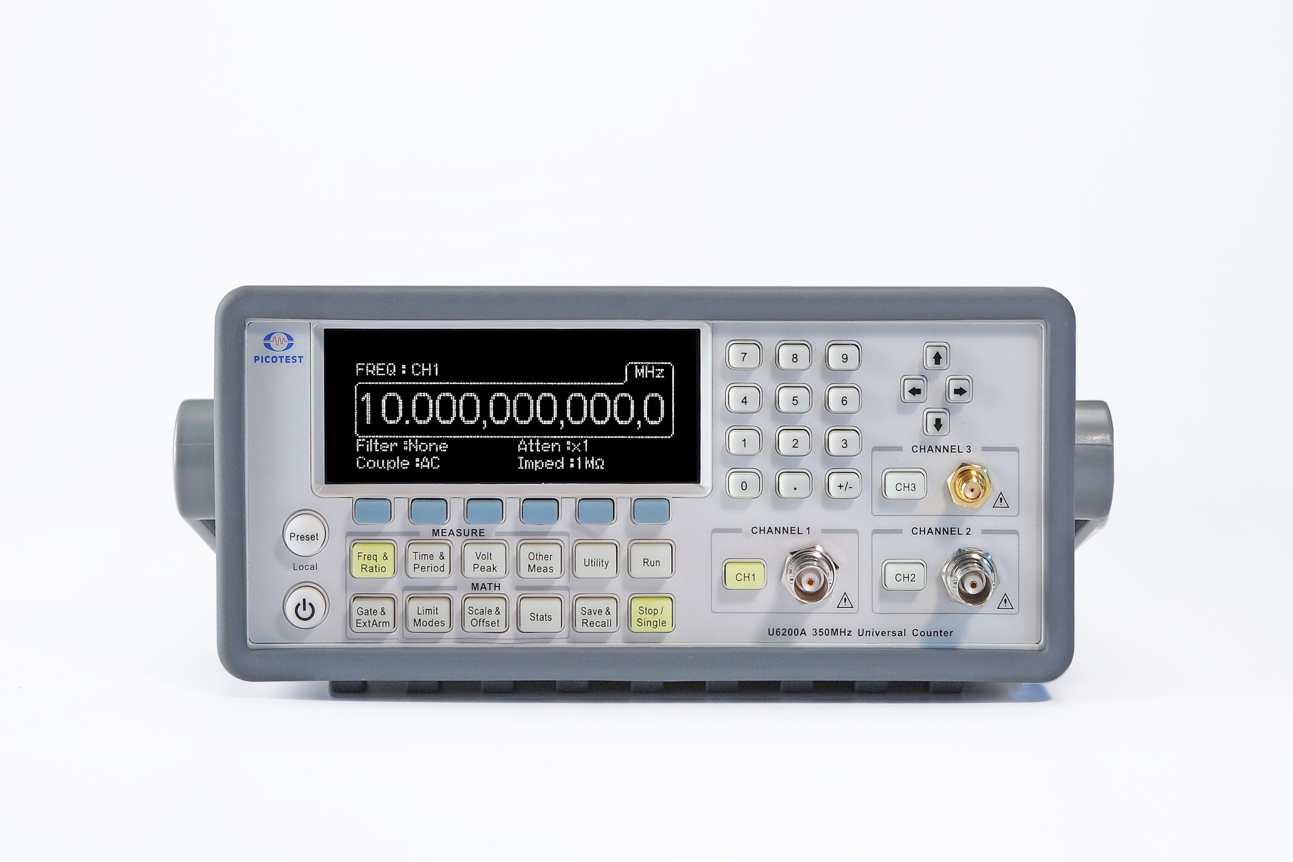
The Picotest U6200A offers a higher frequency capability, better oscillator temperature stability, higher voltage measurement bandwidth, higher resolution and many other benefits compared with the competition. The U6200A CH3 is included free and has a range from 375 MHz to 6GHz. An optional 20GHz module is also available. The rear inputs are not connected to the front panel inputs, allowing up to 5 measurement channels. Other benefits compared with the competition include faster measurements, faster statistics, USB and LAN inputs, better damage protection levels and electronic calibration.
Click here to download a PDF of the complete specifications.
- 12 Digit Resolution
- Easy to use keypad
- 1mHz – 400MHz Ch1 and CH2
- 375MHz to 6GHz on CH 3 included FREE
- 10MHz synchronization included FREE
- Optional rear Inputs are isolated from the front panel allowing 4+1 measurement channels
- 40ps time domain function resolution.
- Time Base Stability: < 1 PPM temperature and
- Optional Oven Stability
- Electronic Calibration
- Statistics & Math Functions
- 20GHz module option available
- SCPI commands are compatible with the Agilent 53132A
12 Digits Resolution & 6 GHz Frequency Measurement
The Picotest U6200A universal counter, whose production procedures conform to ISO 9004, has a frequency resolution of 12 digits per second, 40 ps time interval resolution and a complete set of test and analysis features. The standard U6200A’s CH3 has a range from 375 MHz to 6GHz and the standard CH 1 & 2 has a range from 1 mHz to 400 MHz.
Great Features for Universal Purposes
The Picotest U6200A also provides great features including Frequency & Ratio (11Digits/Sec.), Time interval, Period (2.5 ns to 1000s), Duty Cycle, Pulse Width, Rise/Fall Time, Peak Volts (100 Hz~300 MHz), Phase, Totalize, Temperature Stability (< 1 PPM), Aging Rate (< 2 PPM per year), timebase reference channel and complete Front-End Isolation. Moreover, it offers 20 memory locations for storing frequently-used operations.
Full Math Functions & Easy Operation Panel
The Picotest U6200A offers built-in statistics and math functions. Users can make measurements, simultaneously measure and report mean, min/max, delta and standard deviation. Scale & offset can be easily used for compensation purpose according to the users’ applications. In addition, in order to obtain these measurements, the user can easily use the numeric buttons to define settings. The U6200 also provides users with visual indications of selected functions.
Fast Measurement & Special Application
The U6200A supports real-time digital signal processing technology, which can be applied to analyze data while simultaneously obtaining new readings and speeding measurement. The “Limit Modes” feature is worth to be mentioning since users can set margin according to their specific measurements, and via Go-On or Stop and USB Output settings, the U6200A can continue or stop measuring as a limit is exceeded, and generate an output signal to trigger external devices.
Free Software & Familiar SCPI Commands
Users can obtain data logs via PC software (Microsoft Excel®) using a USB, or an optional GPIB interface. Furthermore, U6200A also supports a webserver function, so users can easily control it via a LAN interface by entering an Ethernet address (Default: 192.168.0.247) on web browsers. In addition, through the SCPI commands compatible with Agilent 53132A, the Picotest U6200A can utilize familiar syntax string for users’ applications. For more command information, please refer to the U6200A User’s Manual in Chapter 7.
Accessories
- High stability oven oscillator module : U6200-OPT01
- 250MHz-20GHz RF module : U6200-OPT02
- Rear Input (CH1/2) module : U6200-OPT04
- Rear panel input module — CH1/2/3 : U6200-OPT05
Specifications | Channel 1 & 2 Input Specifications | DC Coupled | 1 mHz to 400 MHz | AC Coupled | 200 KHz to 400 MHz (50Ω)
30 Hz to 400 MHz (1MΩ) | FM Tolerance | FM Tolerance: 25% | Voltage Range and Sensitivity | 1mH to 225 MHz | 20 mVrms to ± 5 V ac + dc (Medium and High)
25 mVrms to ±5 V ac + dc (Low)
(75 mVrms with optional rear connectors) | 225mH to 400 MHz | 30 mVrms to ± 5 V ac + dc
(75 mVrms with optional rear connectors) | Channel 1 & 2 Input Characteristics | Impedance
1 MΩ or 50 Ω | (ATTx1, 1 MΩ Capacitance) | 24pF | (ATTx10, 1 MΩ Capacitance) | 15pF | Coupling | AC or DC | Low-Pass Filter | 100 KHz (or disabled)
-20 dB at > 1 MHz | Input Sensitivity | Selectable between Low, Medium (default), or High Medium is approximately 1.35x High Sensitivity, low is approximately 1.7x High Sensitivity | Internal Noise | 200uVrms(typical) | Voltage Range and Sensitivity (Single-Shot Pulse) | 1.5ns to 10ns Pulse Width | 80 mVpp to 10 Vpp
(150 mVpp with optional rear connectors) | >10 ns Pulse Width | 50 mVpp to 10 Vpp
(150 mVpp with optional rear connectors) | Trigger Level (ATT x 1) | Range | ±5.125V | Accuracy | ±(15mV + 1% of Trigger Level) | Resolution | 2.5mV | ATT x 10 Range | x10 | Trigger Slope | Positive or Negative | Auto Trigger Level | Range | 0 to 100% in 1% Steps | Frequency | Peak Voltage Fast Mode > 10 KHz
Peak Voltage Slow Mode > 100 Hz
Amplitude > 100 mVpp (No Amplitude Modulation) | Damage Level | DC ~400MHz 50Ω | 12 Vrms | 0 to 3.5 kHz, 1MΩ | 350 V dc + ac pk | 3.5 kHz to 100KHz, 1 MΩ | 350 V dc + ac pk linearly derated to 12 Vrms | 100KHz to 400MHz, 1MΩ | 12 Vrms | Attenuator | Voltage Range | x10 | Trigger Range | x10 | Channel 3 Input Specifications | Frequency Range | 375 MHz to 6 GHz | Channel 3 Input Characteristics | Impedance | 50 Ω | Coupling | AC | VSWR | < 2.5:1 | Power Range and Sensitivity (Sinusoid) | 375 MHz to 500 MHz | -16 dBm to +15 dBm | 500 MHz to 1 GHz | -20 dBm to +15 dBm | 1 GHz to 2 GHz | -23 dBm to +15 dBm | 2 GHz to 4 GHz | -25 dBm to +15 dBm | 4 GHz to 5 GHz | -21dBm to +15 dBm | 5 GHz to 5.5 GHz | -20 dBm to +15 dBm | 5.5 GHz to 6 GHz | -17 dBm to +15 dBm | Damage Level | +25 dBm, DC ±12V | Option Channel 3 Input Specifications (U6200-opt02) | Frequency Range | 250 MHz to 20 GHz | Option Channel 3 Input Characteristics (U6200-opt02) | Impedance | 50 Ω | Coupling | AC | VSWR | < 2.5:1 | Power Range and Sensitivity (Sinusoid, at 25ºC) | 250-500MHz | -22~+23dBm | 0.5-14GHz | -27~+23dBm | 14-15GHz | -21~+23dBm | 15-16GHz | -19~+23dBm | 16-19GHz | -17~+23dBm | 19-20GHz | -13~+23dBm | Damage Level | +26 dBm, DC ±24V | External Arm Input Specifications | Signal Input Range | LVTTL and TTL compatible | Timing Restrictions | Pulse Width | > 50 ns | Transition Time | < 250 ns | Start-to-Stop Time | > 50 ns | Damage Level | 12 Vrms | External Arm Input Characteristics | Impedance | 1 kΩ | Input Capacitance | 17 pF | Start Slope | Positive or Negative | Stop Slope | Positive or Negative | Notes | 1. External Arm is available for all measurements except Peak Volts.
2. External Arm is referred to as External Gate for some measurements. | Internal Time Base Stability | | | Standard
(0° to 50°C) | High Stability Oven
(U6200-opt01) | Temperature Stability
(referenced to 25°C) | ± 1 x 10E-6 | ± 5 x 10E-9 | Aging Rate | Per Day
| | ± 8 x 10E-10 | Per Month
| | | Per Year | ± 2 x 10E-6 | ± 8 x 10E-8 | Turn-on stability vs. time (30
min.) | | ± 2.0 x 10E-8
(referenced to 24 hours) | Calibration | Electronic | Electronic | External Time Base Input Specifications | Voltage Range | 200 mVrms to 10 Vrms | Damage Level | 12 Vrms | External Time Base Input Characteristics | Threshold | 0 V | Impedance | 1 kΩ | Input Capacitance | 25 pF | Input Frequency | 10 MHz | Internal vs. External Time
Base Selection | Manual | Select Internal or External | Automatic | Internal used when External not present (default) | Time Base Output Specifications | Output Frequency | 10 MHz | Voltage | 570 mVpp (0 dBm), typical | Impedance | 50 Ω (typical), AC coupled | Measurement Specifications | Frequency, Period
Channel 1 and 2 | 1 mHz to 400 MHz (2.5 ns to 1000 s) | Trigger | Default setting is Auto Trigger at 50 % | “Auto” Gate Time | 0.1 sec | STD CH 3 | 375 MHz to 6 GHz (0.166 ns to 2.6 ns) | Frequency Ratio | CH 1/ CH 2, CH 1/ CH 3, CH 2/ CH 1, CH 3/ CH1 | (Measurement is specified over the full signal range of each input.) | Results Range | 10E-10 to 10E+11 | “Auto” Gate Time | 0.1 sec | Time Interval | Measurement is specified over the full signal ranges of Channels 1 and 2. The width of the pulse must be greater than 1 ns, frequency range to 300 MHz. | Trigger | Default setting is Auto Trigger at 50 % | Results Range | -0.5 ns to 10E+5 s | Resolution | 40 ps | RMS Resolution | 120 ps | Systematic
Uncertainty | ±(TI × Time Base Error) ± Trigger Level Timing Error ± 500 ps Differential Channel Error | Pulse Width Time | Measurement is specified over the full signal range of Channel 1. The width of the pulse must be greater than 1 ns frequency range to 300 MHz). | Pulse Selection | Positive or Negative | Trigger | Default setting is Auto Trigger at 50% | Results Range | 1.5 ns to 10E+5 s | Resolution | 40 ps | RMS Resolution | 120 ps | Systematic
Uncertainty | ± (Pulse Width Time x Time Base Error) ± Trigger Level Timing Error ± 500 ps Differential Channel Error. | Rise/Fall Time | Measurement is specified over the full signal range of Channel 1. The width of the pulse must be greater than 1 ns frequency range to 300 MHz). | Edge Selection | Positive or Negative | Trigger | Default setting is Auto Trigger at 10% and 90% | Results Range | 2 ns to 10E+5 s | Resolution | 40 ps | RMS Resolution | 120 ps | Systematic
Uncertainty | ± (Edge Time x Time Base Error) ± Trigger Level Timing Error ± 500 ps Differential Channel Error | Phase | Measurement is specified over the full signal range of each input. The width of the pulse must be greater than 1 ns, frequency range |
|